1 2 3 4 5 6 7 8 9 10 11 12 13 14 15 16 17 18 19 20 21 22 23 24 25 26 27 28 29 30 31 32 33 34 35 36 37 38 39 40 41 42 43 44 45 46 47 48 49 50 51 52 53 54 55 56 57 58 59 60 61 62 63 64 65 66 67 68 69 70 71 72 73 74 75 76 77 78 79 80 81 82 83 84 85 86 87 88 89 90 91 92 93 94 95 96 97 98 99 100 101 102 103 104 105 106 107 108 109 110 111 112 113 114 115 116 117 118 119 120 121 122 123 124 125 126 127 128 129 130 131 132 133 134 135

30

Evidence supporting the use of a linear discrete system model for bipedal control and the details of

model construction are presented later in the thesis (Section 3.6), after the particular choices of

RVs and LPPs have been described.


The key to using the linear predictive model for determining the correct control action is the

following.

Once the linear discrete system model has been constructed, the control perturbation

scalings required to drive Qi+1to a desired value, can be computed using the inverse model:

Ki=J-1DQid
+1

(3.11)

where [!]Qid
+1= Qnom- Q
cycle.id
+1, the desired change in the RVs with respect to Qnomfor the current


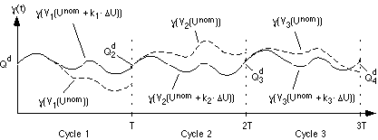
Figure 3.5 shows the limit cycle viewed as state trajectory with respect to time. Three consecutive

controlled cycles of a 1D discrete system are shown in this diagram, Tis the cycle period, kiis the

perturbation scaling for cycle i, and Viis the resulting state trajectory for cycle i. In this example,

Q
id
+1, the desired RV value for each cycle, is held constant for all three cycles.

IMAGE Imgs/thesis.final.w634.gif

t

Figure 3.5 - Three cycles of a typical 1-dimensional system.
In this case, each cycle has the same period, T.


Our control formulation assumes the following apriori information, supplied by the user:

  1. the open-loop control, Unom.

[CONVERTED BY MYRMIDON]