1 2 3 4 5 6 7 8 9 10 11 12 13 14 15 16 17 18 19 20 21 22 23 24 25 26 27 28 29 30 31 32 33 34 35 36 37 38 39 40 41 42 43 44 45 46 47 48 49 50 51 52 53 54 55 56 57 58 59 60 61 62 63 64 65 66 67 68 69 70 71 72 73 74 75 76 77 78 79 80 81 82 83 84 85 86 87 88 89 90 91 92 93 94 95 96 97 98 99 100 101 102 103 104 105 106 107 108 109 110 111 112 113 114 115 116 117 118 119 120 121 122 123 124 125 126 127 128 129 130 131 132 133 134 135

64

undesirable, it is also an artifact of using the up vector RV in the lateral dimension. The lateral hip

perturbations which result in this effect are chosen to maintain lateral torso uprightness.

Using a

different choice of RV for the lateral dimension can correct this effect, as will be demonstrated in

Chapter 5.

0.35

0.3

0.25

0.2

0.15
0.1 IMAGE Imgs/thesis.final.w6122.gif
0102030405060

step

IMAGE Imgs/thesis.final.w6123.gif

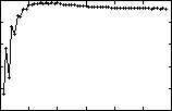
Figure 4.7- Step length vs step number.
Q
d= [0.25,0] walk of Figure 4.3 (b)

One final characteristic of the walks is excessive front-to-back and side-to-side motion of the

torso. This body motion is a result of the particular choice of control perturbations.

and a suitable solution will be discussed in Section 4.4.

This effect

4. 2

Swing-COM Regulation Variables

Our balance control technique is also effective with the use of swing-COM RVs.

The fact that

significantly different choices of RV can be used successfully with otherwise identical control

serves to illustrate that the proposed control approach is reasonably general.

Figure 4.8 shows a representative set of RV trajectory plots for the swing-COM vector trials.

The

plots indicate the trajectories of both feet through the whole cycle since the swing leg, and hence

the swing-COM RV, changes legs each step. In contrast with the similar up-vector trajectories of

Figure 4.2, the swing-COM-based RV trajectories do not exhibit "strong" limit cycle behaviour,

[CONVERTED BY MYRMIDON]